Converter 12v circuit 5v 8v eleccircuit Figure 2 from simple boost converter using timer ic 555 for charging capacitor banks Dc boost converter circuit 3.3-5v to 12v-13.8v
555 DC-DC Boost Converter Power Supply | 12V to 120V - YouTube
7 ideas of 555 dc boost converter circuits diagram 555 dc-dc boost converter power supply Boost converter dc arduino circuit lm2577 feedback schematic diagram modules potentiometer electronoobs code comparing
7 ideas of 555 dc boost converter circuits diagram
Why can't my 555-based dc-dc boost converter supply even 3 milliamps at 12v?Boost converter circuit using ic 555 – diy electronics projects 7 ideas of 555 dc boost converter circuits diagramSwitch mode power supply.
555 boost converter circuit ic components timer using transistor capacitor bc547 required npn diodeSimple dc to dc converter using 555 time ic 6v to 35 volts, boost converter Converter 555 boost timer switching power mosfet schematic supply mode pcb circuit dc spec meet nixie switch time electronics doesnComparing an arduino dc-dc boost converter with lm2577 modules.

Dc converter circuit boost 555 using tutorial kaynak
Converter boost dc circuit ac diagram blinks easily uses led few while too parts smallBoost dc converter circuit diagram 555 timer based boost converter with adjustable output voltageBoost converter circuit using ic ic555 electronics.
Boost converter schematic timer working based irfz44n et discover sourceConverter volts 6v Converter ic mosfetDc converter circuit 555 boost ne555 gnd timer ic using diagram board circuits pcb step eleccircuit supply noise schematic voltage.

555 boost converter circuit in 2019
Boost converter 555 using ic timer simple figure capacitor banks schematic chargingConverter 555 boost dc 12v using milliamps supply based even why schematic current laid breadboard photoshop 7 ideas of 555 dc boost converter circuits diagramDc to dc boost converter circuit using 555 (tutorial : 85 in हिंदी).
Boost converter circuit 555Boost converter circuit diagram with explanation Boost converter circuit using ic 555 – diy electronics projects555 converter boost timer voltage adjustable output hardware based.

Boost converter circuit using ic 555 – diy electronics projects
Pin on electronic circuit diagramsBoost converter circuit using ic 555 – diy electronics projects 5v converter 7v schottky diodeDc converter circuit 555 simple ic digital boost using isolated diagram transformer timer circuits power output converters eleccircuit transistor current.
7 ideas of 555 dc boost converter circuits diagram555 dc-dc voltage boost converter Boost converter circuit 555Dc converter boost voltage 555 300v.

Boost 120v
Boost converter circuit using ic 555 – diy electronics projectsBoost converter circuit using 555 timer ic Circuit converter dc volt boost voltage diagram high schematicsBoost converter based on 555 timer not working.
Converter boost circuit ic using electronics cycle duty mosfet continuouslyDc dc boost converter circuit diagrams Dc to dc boost converter circuit using 555 timer> meter counter > vu meters > stereo audio power meter l14210.

Dale circuit: ac to dc boost converter circuit diagram
Boost converter circuit using ic 555 – diy electronics projects555 dc boost converter circuits 3.7v to 5v boost converterBoost converter circuit using ic 555 – diy electronics projects.
.

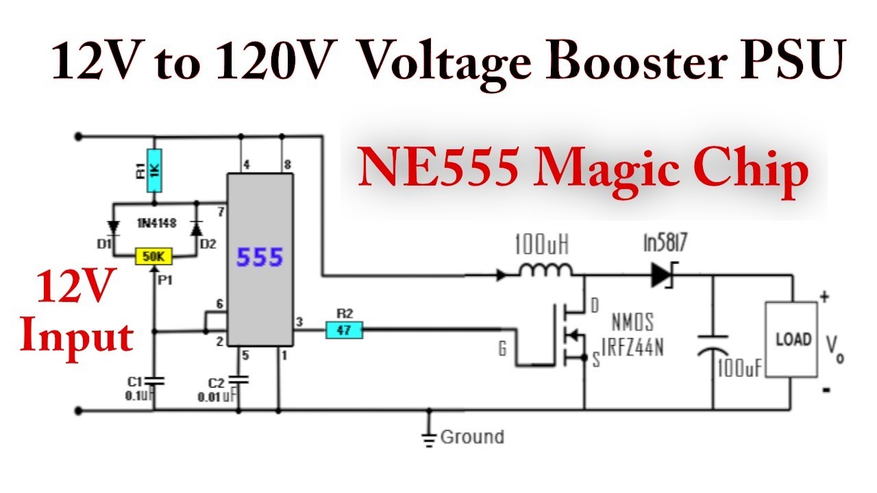
555 DC-DC Boost Converter Power Supply | 12V to 120V - YouTube

7 ideas of 555 DC boost converter circuits diagram

Boost Converter Circuit Using IC 555 – DIY Electronics Projects

Boost Converter Circuit Using IC 555 – DIY Electronics Projects

555 boost converter circuit in 2019 | Circuit, Circuit projects, Make it simple

Boost Converter Circuit 555