Please, design a 4-bit binary adder-subtractor. yo... Design 4 bit parallel adder and subtractor Használható melbourne tömör 4 bit subtractor truth table zenei ban ben mániás
CircuitVerse - 4 Bit Parallel Adder/Subtractor
Digital logic Circuit diagram of 4 bit adder subtractor using ic 74836 Adder subtractor bit circuitverse composite
Digital logic design: binary parallel adder/subtractor
Adder serial subtractor module schematics4 bit adder subtractor circuit diagram Adder subtractor binary vhdlAdder bit signed alu unsigned complement cs adders lab note both.
Adder circuit diagram schematic bit works figure4 bit full adder circuit Digital logicSolved: consider the 4-bit adder/subtractor circuit displa....

Cs 3410 spring 2016 lab 1
Logic adder subtractor parallel binary circuit bit diagram mode control digital signal determines whichAdder serial subtractor flop flip vhdl registers schematics simplified Adder bit circuit subtractor ripple carry logic diagram using project only digital computing learn let its build indie electronicsAdder subtractor bit circuit add sub overflow complement logic detection carry designing control addition digital line questions zero computer define.
Let's learn computing: 4 bit adder/subtractor circuitAdder subtractor bit binary please electrical engineering modular con chegg answers questions Solved design a 4-bit adder/subtractor using the 7483 and4 bit binary subtractor circuit diagram.

Adder bit subtractor four ripple ppt powerpoint presentation ou sonoma pcb produce engineering jack science university own state board slideserve
Full-adder circuit, the schematic diagram and how it works – deeptronicSolved build the adder-subtractor circuit from page 18 from Demo: 4-bit adder subtractor using full adder ic with tinkercad4-bit parallel adder/subtractor.
Adder subtractor vlsi7483 adder bit subtractor using circuit binary diagram input gates subtract logic solved complement block answer problem been add parallel Circuit design 4-bit binary adder/subtractorAdder subtractor logic.

Solved adder and subtractor 4 bit circuit i have the next
[coa 55] 4 bitWhat is the application of a half subtractor? 4 bit adder circuit diagram4-bit serial adder/subtractor with parallel load – altynbek isabekov.
Bit adder subtractor circuit values consider following input help mode steps solve thank displayed figure questions solvedSubtractor bit adder Chinmay oliSubtractor adder circuit bit using logisim pint schematic.

Circuit diagram of 4 bit adder subtractor using ic 74836
Adder subtractor tinkercadLesson 13 binary adder subtractor in vhdl How to design a four bit adder-subtractor circuit?4 bit binary adder subtractor circuit diagram.
Circuit design 4 bit parallel adder subtractor with bcd 7 segment_group 24-bit serial adder/subtractor with parallel load – altynbek isabekov .


4-Bit Parallel Adder/Subtractor | Elétrica

What is the application of a half subtractor? - Quora

PPT - Four-Bit Adder- Subtractor PowerPoint Presentation - ID:4278806
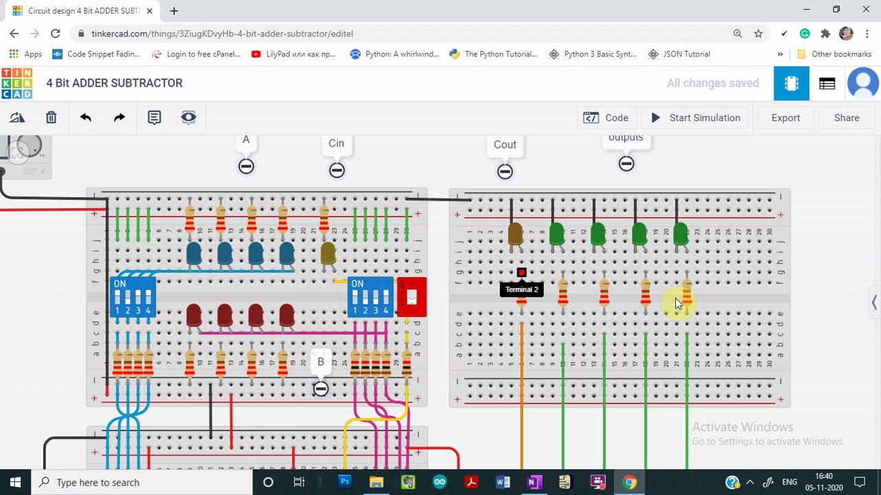
Demo: 4-bit Adder Subtractor using Full Adder IC with tinkercad - YouTube

4 Bit Binary Subtractor Circuit Diagram - Wiring Draw

Let's Learn Computing: 4 bit Adder/Subtractor Circuit

Solved: Consider The 4-bit Adder/subtractor Circuit Displa... | Chegg.com